Help Installing Nest Thermostat on Millivolt System Using 24v Transformer
January 22, 2012 2:40 PM Subscribe
I just purchased a new Nest thermostat. My old thermostat gets power from an ancient millivolt system (thermopile on top of pilot light generates 0.7VDC). This is incompatible with the Nest, since the Nest requires standard 24VAC. Nest support told me they've heard some customers have had success using 24v step-down transformer. After lots of research, I think the wiring is supposed to go something like this:
W from furnace (common, -0.7VDC ?) --> W on T-Stat
24 VAC power from transformer (+/- ?) --> C on T-Stat
R from furnace (+0.7VDC ?) --> RH on T-Stat
24VAC power from transformer (+/- ?) --> RH on T-Stat
As you can see, I'm still a bit fuzzy on the details. Questions are below the fold!
• Which of the 24v wires (+/-) coming out of the transformer go to which terminal on the Nest (C, Rh)?
• Is it really okay that the 0.7VDC furnace/millivolt Rh wire and one of the 24VAC transformer wires will be on the same Rh connector on the Nest? If I understand correctly, the reason it doesn't matter that I'll have two wires on the Rh connector is because they are part of two different circuits--is that right?
• Can I just buy any of the many 24v step down transformers out there, or am I looking for something specific? Does the VA rating matter?
Alright, I am not in any way qualified to deal with HVAC wiring, but we did just install a different sort of thermostat on a different wiring regime. So, why do you think you need to connect the 24V/C to the RH terminal? The 24V wire goes only to C on ours.
posted by thirteenkiller at 3:16 PM on January 22, 2012
posted by thirteenkiller at 3:16 PM on January 22, 2012
Response by poster: It was also my initial thinking that it'd be bad to put the 24VAC on the Rh, since the other would be expecting 0.7VDC, but based on the forums posts I found, it sounds like it's okay. Here are the specific quotes from the forum posts where I got the idea about plugging two wires into the Rh terminal:
"Many millivolt systems run fine with the millivolt gas furnace connected to RH and W and adapter connected to RH and C. Only one wire from both systems are connected to RH so there is no electrical interference with each other. Just keep the wire from the adapter going to C from touching any other wire."[1]
"Connect a 12 VAC or DC or an 18VAC adapter from radio shack to the C terminal and the RH terminal. Yes it is OK for 2 wires be connected to the RH as long as the other two (W and C) don't touch."[2]
"I finally got an answer from an engineer at WayneDalton who bought the Intermatic CA8900. She said that the 24volt transformer wire to the RH terminal would not effect the RH wire back to the gas stove. hope she is right" [3]
I admit I'm not really sure why I need 24VAC on both the RH and C terminals, instead of just the C terminal, but at least now you know where I got the idea!
Even assuming the above is correct though, I still don't know the answers to the questions below:
• Which of the 24v wires (+/-) coming out of the transformer go to which terminal on the Nest (C, Rh)?
• Can I just buy any of the many 24v step down transformers out there, or am I looking for something specific? Does the VA rating matter?
Thank you both for your help thus far!
Forum posts:
[1] http://forums.radiothermostat.com/viewtopic.php?f=12&t=5756
[2] http://forums.radiothermostat.com/viewtopic.php?f=10&t=2893&start=0
[3] http://www.contractortalk.com/f6/powering-24v-millivolt-thermostat-control-gas-stove-105411/
posted by jesseendahl at 3:58 PM on January 22, 2012
It is my understanding that polarity doesn't matter for these terminals.
I have found other forum posts that confirm the RH + C wiring thing you found, so it does seem plausible although I don't understand it exactly.
That's all I know! Please check this with other sources, because my only expertise is due to a couple hours' frantic searching on Google as my house started to get very cold.
posted by thirteenkiller at 4:16 PM on January 22, 2012
Response by poster: killinthirteen: It looks like you're right about the polarity. I think I just found the answer in a Youtube instructional video! I've included a link to the video at the 3:10 marker below:
C Wire - How to power the thermostat via an additional transformer.
Quote: "You would simply take one of the two [transformer wires]. Doesn't matter which one. One will go to the C terminal... [and] the second wire will be added to the Rh terminal. You may already have a wire in the Rh [terminal] from your furnace. That is okay. It will just be added to it. It will not interfere with it."
As far as the amperage of the transformer goes, the video description states: "Recommend power rating 24 volts AC at .5 amps."
So I think this transformer will do the trick. And it has the added bonus of having a built-in breaker, which is a big plus.
Thanks again for your help everyone!
posted by jesseendahl at 4:25 PM on January 22, 2012
Response by poster: Oops, this just in from the other place I posted the question:
"IF you have a milivolt system then you can not do that! When Rh and W are shorted that connects the milivoltage produced by the thermopile is transferred from the Rh wire to the W wire which connects to the gas valve completing the circuit. If you were to interject 24VAC on the Rh terminal you could ruin the gas valve."
posted by jesseendahl at 4:56 PM on January 22, 2012
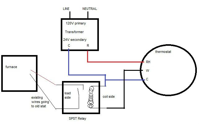
Response by poster: The latest is that I might need a "spst relay (24VAC coil)," but I don't understand how that would work or where it would fall in the wiring diagram. If anyone out there knows, please share!
posted by jesseendahl at 5:49 PM on January 22, 2012
posted by jesseendahl at 5:49 PM on January 22, 2012
Best answer: It is possible that what you are trying will work, depending on how the thermostat is designed.
The reason is that there are two independent circuits. Remember that current has to flow in a complete circle. Drawing it out on paper may help.
The first circuit connects one terminal of the transformer to RH, through the thermostat, out C and back to the other terminal of the transformer. That provides 24VAC between the RH and C terminals and powers the computer circuitry of the thermostat.
The other circuit is furnace thermopile to RH, through the thermostat heat switch, out the W terminal to the gas valve which is grounded to the other side of the thermopile. This circuit sees only the 750 mV of the thermopile. Since there is no connection between the gas valve/thermopile and both terminals of the transformer, this circuit does not see the 24VAC.
This means that making the connections as you propose should work. Just make sure that the C wire connects only to the thermostat and to the transformer and is not grounded to anything else in the system. Since the 24V is AC and not grounded, it doesn't matter which terminals you connect to RH and C.
As a side note, on a more typical 24VAC system, one terminal of the transformer connects to RH and the other terminal of the transformer connects both to the C terminal and the gas valve through the W terminal. So in this case, 24VAC goes through both circuits. So how does the thermostat computer get power if there is no C wire on a 4-wire system? In this case the power for the computer is generated by the connection between RH and W. This current is the same that would turn on the gas valve, but when the heat switch is open, only a tiny amount of current flows to provide power to the computer, not enough current to activate the gas valve.
Since your 24VAC transformer is only providing a tiny amount of power to the thermostat computer, your transformer is way overkill. Instead of 50 watts you probably only need 1 watt since the transformer is not powering the relays in the furnace, only the computer chip. So you could use a much smaller transformer but the one you selected is okay.
posted by JackFlash at 6:15 PM on January 22, 2012
Response by poster: JackFlash: That's what I thought! Thank you very much for your thorough explanation. Do you know why someone would suggest this design utilizing an SPST relay instead?
posted by jesseendahl at 6:30 PM on January 22, 2012
posted by jesseendahl at 6:30 PM on January 22, 2012
Best answer: By the way, one way to test this is to first connect the transformer to RH and C. This should provide power to the thermostat computer. Also connect RH to R on the furnace. This provides the thermopile voltage to the heat switch. Do not connect the white wire. This will prevent any possible damage to the gas valve. Then adjust the thermostat to turn on heat which closes the switch on W. You probably will hear a click as the switch closes. Measure the AC voltage between W terminal and the white wire. It should be 0. Then measure the DC voltage between the W terminal and the white wire. It should be about 750 mV DC (assuming the pilot light is on). Next adjust the thermostat to turn off heat. Both AC and DC voltage between W and the white wire should be 0. If so, hook up the white wire and you are good to go.
The SPST relay method will work, but shouldn't be necessary if the thermostat is designed as expected with the W and C terminals isolated.
posted by JackFlash at 6:55 PM on January 22, 2012
The SPST relay method will work, but shouldn't be necessary if the thermostat is designed as expected with the W and C terminals isolated.
posted by JackFlash at 6:55 PM on January 22, 2012
Response by poster: JackFlash: Perfect. As soon as I get the Nest (it should arrive Tuesday), I will go through and measure step by step with the multimeter as you suggest. As far as the transformer goes, I am having a surprisingly hard time finding one with a low VA/wattage. Do you have any suggestions on where to look? Thanks again. You've been a HUGE help.
posted by jesseendahl at 8:22 PM on January 22, 2012
posted by jesseendahl at 8:22 PM on January 22, 2012
I would probably just use a 12 VDC adapter from RadioShack. The 24 VAC goes through a bridge rectifier to make DC which is then probably regulated down to either 3.3V or 5V so a 12VDC input should work. It's cheap and it shouldn't hurt anything.
But ---
A couple suggestions. That Nest thermostat seems to be way, way expensive. You can get something equivalent from Honeywell for only $50 or $60.
Second, if you have a millivolt furnace, it must be really old. You should consider replacing it with a newer furnace. You could go from 40% to 60% efficiency to 80% to 90% efficiency. It could pay for itself in just a few years in cheaper heating bills.
posted by JackFlash at 9:34 PM on January 22, 2012
Response by poster: JackFlash: Thanks for the suggestions. Unfortunately we are in an apartment, so we can't make those types of upgrades. I can only do this upgrade because all the wiring is exposed, and all it's going to take in terms of alterations to the building is two screws inside my closet to mount the transformer. One of the reasons we specifically want the Nest is for safety re: the floor furnace. The Nest has motion sensors/auto away functionality and ability to remote control via iPhone app. This is important because about a week ago, the dog dropped a tennis ball on the floor furnace while we were watching a movie, and the whole room filled with smoke before we noticed. We managed to catch it since we were home, but it'd be great to have the thermostat shut off the heat automatically if we forget to do so, and also great to have the ability to shut it off even faster via the iPhone app (e.g. if we remember that we forgot to turn it off when we're half way to our destination).
On a related note, I upgraded our fire alarm to a dual sensor (ionizing/photoelectric) model so that it will better detect smoldering fires.
posted by jesseendahl at 10:36 PM on January 22, 2012
On a related note, I upgraded our fire alarm to a dual sensor (ionizing/photoelectric) model so that it will better detect smoldering fires.
posted by jesseendahl at 10:36 PM on January 22, 2012
Response by poster: For anyone wondering how much power the Nest pulls: 2.1Wh over 3.7V. That's according to Sparkfun's teardown of the Nest.
posted by jesseendahl at 11:53 PM on January 22, 2012
posted by jesseendahl at 11:53 PM on January 22, 2012
Best answer: The install was a success! I followed JackFlash's wiring instructions and it works like a charm. For anyone wondering, the numbers I posted above for the power are incorrect. The correct numbers were attained from a user named SESteve, who posted this at the other forum where I asked this question:
I heard back from Nest support. They said "Nest draws between 30mA – 100mA, where 100mA is the optimum amount." That's pretty minimal. The transformer I ended up using supplies up to 1A, so it's plenty for the job.posted by jesseendahl at 8:19 PM on February 8, 2012
The instructions worked for him as well, with his free-standing propane stoves.
Here is the transformer I ended up using this Rheem Ruud Weatherking Factory transformer since I wanted to mount it on a standard 4x4 electrical box next to an existing light inside my closet.
Best answer: I will say one last thing—due to the way the Nest is designed, it's impossible to plug two wires into the Rh terminal, so you'll need to do a pigtail wire splice: two Rh wires come into wire nut, one combined Rh wire goes out into the Nest Rh terminal.
Rh furnace wire ------------>
wire nut ----------------> Combined Rh wire to Nest
Rh transformer wire ------->
All three wires are twisted together inside the wire nut. It's super simple.
...
Note also that I didn't end up using the multimeter since a) I couldn't get the probes into the terminals and b) when you snap the actual Nest onto the back panel, you completely close off access to the wiring terminals. So if you did want to test with a multimeter first, I believe you'd have to do a bunch of pigtails so that you could have the wires connected to the Nest terminals inside and have wiring available outside the unit for testing at the same time.
posted by jesseendahl at 8:35 PM on February 8, 2012
« Older Help me clean and protect these wood floors | I can't convince my anxiety-afflicted mom to get... Newer »
This thread is closed to new comments.
W from furnace (common, -0.7VDC ?) --> W on T-Stat
24 VAC power from transformer (+/- ?) --> C on T-Stat
R from furnace (+0.7VDC ?) --> RH on T-Stat
24VAC power from transformer (+/- ?) --> RH on T-Stat
posted by jesseendahl at 2:48 PM on January 22, 2012