DIY Forced-Perspective wall-hanging art/mathematics advice sought.
January 9, 2009 4:39 AM Subscribe
3-D folks, Mathematicians, and Artists: Trying to create my own Trompe-l'œil / forced perspective illusionary image to hang on my wall (e.g. the awesome parking garage signage everyone's already seen... more examples here, and here). I'm having trouble faking it with 2-D programs, and the math is puzzling me.
So without going into too much detail, here are the facts:
1. Wanting to put artwork in a simple 90°/90°/90° corner where two walls meet a ceiling.
2. In theory: My ugly corner, plus this nice logo [svg d/l], equals this cool effect when viewed from the correct angle.
3. "correct angle" is pillow-height from the head of my bed... perhaps best visualized in this map/schematic/layout.
Having no proficiency of any kind in any 3-D package (which I suspect might make this quite easy), I resolved to figure it out with pencil and paper and then distort the three sections of the image accordingly by using a vector 2-D program (with which I do have "B-" proficiency). After many pitched hours of re-learning long-lost trigonometry (no sweat, really... glad for the opportunity), I have hit a brick wall that I need help breaking through. I suspect that there is a way to do this in Illustrator, but I'm at a loss for what it might be. CS2's neutered "3-D effects" were of no use to me either.
So, in summary: This is how the image is divided visually (just a sketch... not exact), and these are the wall assignments for each of the three pieces. I suspect that the final product will be distorted in ways superficially resembling this (completely speculation and not anything close to exact... visual reference only). Need to find a way -- hopefully repeatable, and ideally customizable to other viewing angles/corners -- to output this into three "distorted" vector files to be run on a plotter.
If anyone's got some advice to go on, I'd be very appreciative. If additional measurements/project files/clarifications would help, please do let me know. If I can find some easy and explainable way to pull this off, I'll throw a tutorial up on Instructables or something to help anyone who has a similar project/idea in the future. Thanks a ton.
(I know I could just do the old "Trace the projected transparency onto the wall" trick, but I was wanting to cut this out of vinyl on a plotter... and for that I'm going to need 3 vector files... one for each wall.)
You reminded me of the pavement art of Julian Beever with this, and I followed a few links to this Wikipedia article which talks about placing an image on a grid and distorting them -- in his case, just lengthening them I suppose (without the involvement of corners), but I wonder if applying a grid might help somehow. I'm not mathmatical so that's as far as I can think about it. ;)
What would happen if you took a photograph of the corner you're wanting to put it in, from the "sweet spot" you want to view it from, plop that into Illustrator as a background layer, and then cut your image into three and distort them as necessary to look right against the backdrop of that image?
posted by springbound at 5:27 AM on January 9, 2009
Hang on wait, that doesn't make sense at all. You'd need to take photos of your individual planes, front on, and then distort THOSE in Illustrator (with your warp tool or similar) until you saw the desired effect. But could THAT work?
posted by springbound at 5:30 AM on January 9, 2009
posted by springbound at 5:30 AM on January 9, 2009
(Dumping, of course, the three parts of your logo onto the warped walls, and then "unwarping" them all together back til they resembled "front-on" again. I'm going to shut up now.)
posted by springbound at 5:32 AM on January 9, 2009
posted by springbound at 5:32 AM on January 9, 2009
I'm with b33j. I used to watch a DIY show with a Canadian lady where she was always painting interesting murals, and she would always just project the images on whatever surface she was working on in order to get the right perspective. She once did one where it looked like some sort of big cat was coming at you when you rounded a corner, and she just moved the projector around so that from the position the image was head on, but from the other end of the hall, it looked like a stretched out cat.
posted by bluefly at 5:42 AM on January 9, 2009
posted by bluefly at 5:42 AM on January 9, 2009
Response by poster: How did she get the vector files I need for my plotter?
posted by jjjjjjjijjjjjjj at 5:49 AM on January 9, 2009
posted by jjjjjjjijjjjjjj at 5:49 AM on January 9, 2009
Oh, sorry. The tiny writing in your question is super small on my computer, so I misread it. (Maybe important information germane to the question shouldn't be so small?) She did use a computer program to produce templates of the image to stencil, but I have no idea what it was. I'm sorry I was so unhelpful.
posted by bluefly at 6:15 AM on January 9, 2009
posted by bluefly at 6:15 AM on January 9, 2009
Response by poster: (Not a problem... Meant it in a "playfully chiding" way, but the tone might've been way off. I see how that sentence might've seemed a bit dick-ish as it was delivered. I apologize.)
posted by jjjjjjjijjjjjjj at 6:18 AM on January 9, 2009
posted by jjjjjjjijjjjjjj at 6:18 AM on January 9, 2009
How far did you get working out the math? I think that's probably going to be the fastest way; work out the distortion function and use something like Matlab/Octave to apply it to the data.
As for vector files, I guess the big problem is that the distortion is going to trash the vector information--the circle won't be a circle anymore, the splines/beziers making up the text may or may not remain splines/beziers after the transformation (not sure without looking at the math), etc. Two possible fixes:
1. approximate all your curves with polygons, then transform those
2. transform a high-resolution raster image instead, then retrace the vectors
Gotta get back to work right now, but I'll try to remember to come back later and work out the math (if nobody beats me to it).
Or, a rougher way to do it: project the image, then take pictures of the walls face-on, then trace vectors from the photos.
posted by equalpants at 6:20 AM on January 9, 2009
Best answer: Projector is probably the most practical idea.
But you can get the mapping you want by putting more reference points in your photo, and the computer will do all the math...
Example (only using one wall, but you'll get the idea):
1. Use tape to mark a 8.5" x 11" rectangle on the wall.
2. Take a photo.
3. Use a vector drawing program to superimpose the logo inside the rectangle (which will be an irregular diamond in the 2-D photo)
4. In the vector program, distort the diamond until it is once again a rectangle with the correct aspect ratio.
5. The skewed logo inside the rectangle is the correct projection. Print it out and glue it to your wall.
posted by qxntpqbbbqxl at 6:28 AM on January 9, 2009 [1 favorite]
How about starting with something like your example image with the corner taken from the correct angle, with the desired logo placed on top. Then, cut out the three component wall vertex areas, and figure out how to distort those to match the correct spot-on decal-application orientation?
You could print out your sample distortions, paste them into a box corner, and look at them to see if you got it right.
posted by amtho at 6:45 AM on January 9, 2009
You could print out your sample distortions, paste them into a box corner, and look at them to see if you got it right.
posted by amtho at 6:45 AM on January 9, 2009
What I said is almost the same as what qxntpqbbbqxl said. Only without the idea of reference points, which are really what you need to make it work.
posted by amtho at 6:45 AM on January 9, 2009
posted by amtho at 6:45 AM on January 9, 2009
Response by poster: The "using a reference piece of paper of known size, and then reconstituting it" idea is a really, really clever one and I like it quite a bit. Neat workaround and I like the way you think. BUT, I think there's gotta be a way to do this purely mathematically/digitally, and not introduce a (cheap, wide-angle lens, point-and-shoot) camera into the equation to gum up the precision.
(Wasn't just blowing smoke, though... the paper idea is pretty ingenious, and not one that I would've thought of any time soon.)
posted by jjjjjjjijjjjjjj at 6:51 AM on January 9, 2009
(Wasn't just blowing smoke, though... the paper idea is pretty ingenious, and not one that I would've thought of any time soon.)
posted by jjjjjjjijjjjjjj at 6:51 AM on January 9, 2009
you need to find an old book called something like "descriptive geometry." i think the transform you are looking for will be called a "one-point projection."
posted by geos at 7:18 AM on January 9, 2009
posted by geos at 7:18 AM on January 9, 2009
(At some point you'll need to measure things, and a cheap 6-megapixel camera will give you much more precision than a tape measure. You can correct for the wide angle lens by stretching the photo.)
But it's a noble endeavor to want to work out the math =)
You want to project a point P from one plane (containing the apparent logo) onto a point on another plane (the wall). To do this, you want to solve for the point at which the line normal to the logo plane and passing through P intersects with the wall plane.
It is probably easiest to make your coordinate system that of the wall, so you need to measure exactly where the logo appears to be in space, in relation to the wall.
If none of this makes sense, read up on linear algebra, particularly vectors and vector spaces.
posted by qxntpqbbbqxl at 7:42 AM on January 9, 2009
Response by poster: Piecing it together, yes. Searching terms, etc... lots of valuable suggestions thus-far.
But re: At some point you'll need to measure things... What is it that I haven't measured? (Not at all ruling out that I could've missed something -- but I'm not sure what else can be measured. Help me out, here, if you were thinking of something specific.)
posted by jjjjjjjijjjjjjj at 7:59 AM on January 9, 2009
What you haven't measured:
Somewhere in the mathematical model, there are going to be parameters that describe the orientation of the walls with respect to the viewer. You can find the values for these parameters in two ways:
1. work them out with trig, by assuming that the room is a rectangular prism and the viewer is placed at point X inside it, etc.
2. put markings on the walls, take a picture, calculate the angles from the picture
The trouble with #1 is that the walls are not going to be perfectly perpendicular, and you have no way of knowing their angles with respect to each other. The trouble with #2 is that you can only be so accurate when you're drawing markings on the walls. All things considered, though, I agree with qxntpqbbbqxl: #2 will be more accurate.
posted by equalpants at 8:27 AM on January 9, 2009
Response by poster: Blasphemy! The finest bricklayers who ever trod the earth were in Victorian-Era St. Louis. (ah... who the fuck am I kidding. You're right... there's not a plumb line in this house. And the walls are stucco on top of stucco on top of... yeah). Still, though, given a close-to-perfect prism and trig, I'd have enough to rough it in, yes? I'm resigning myself to the notion that it might have to be a bit more of a back-and forth process of subjective refinement -- but I'm not going down without a fight.
posted by jjjjjjjijjjjjjj at 8:45 AM on January 9, 2009
posted by jjjjjjjijjjjjjj at 8:45 AM on January 9, 2009
You aren't going to accomplish this by simply projecting the flat logo and tracing. All you'll get is a logo that conforms to the contours and corners of the walls, resulting in a distorted image, which is exactly what you aren't after. In fact, calling it "forced-perspective" is incorrect since what you are after is NO perspective. The logo should appear flat, as if it is floating in space off the wall.
There is actually a small industry built around just this sort of illusion. It is most commonly seen at sporting events where corporate logos are distorted and painted onto the ground of a field with the exact positioning of a particular tv camera in-mind. The result is a logo that appears correct, rather than distorted by perspective.
According to this very old webpage, the process is called Inverse Perspective Transformation. Googling that term results in a lot of highly technical computing-oriented pages, as well as some patent info.
I have a feeling there is some serious software/computing involved in this.
posted by Thorzdad at 10:19 AM on January 9, 2009 [1 favorite]
Response by poster: You absolutely could (and I and many others have) easily "accomplish that by simply projecting the flat logo and tracing." I've seen a room full of 7th graders do it in an art class with fairly impressive results. Think it through.
That said, I'm not looking to go the tracing route (discussed earlier) for this particular project. As far as "serious software/computing" being required, I would think no more serious than any run-of-the-mill desktop 3d package. I'm not thinking that the barrier was anything more serious than the fact that my brain reboots every 2 minutes if you give it a z-axis to contend with.
Side Note: The signs you see on cricket and soccer pitches were simply perspective-distorted normal field markings relying on long shots with a locked-down camera (1st generation), or a fairly simple tweak on a chroma-key with on-field reference points for image stabilization (current gen). Pretty amazing final product, but hardly anything arcane enough to justify awed confusion. Let's just say that one passenger-aircraft disaster isn't sufficient to rob the world of the brainpower needed to run the "First and Ten" system. sigh of relief
posted by jjjjjjjijjjjjjj at 11:19 AM on January 9, 2009
Okay, here's an outline of the math. This is using a "pinhole camera", which is not very fancy but hopefully should work well enough.
Imagine we're projecting the logo onto the walls from a transparency, and for now let's just focus on one of the walls, since the process will be the same for all three. There are three coordinate systems we care about: the 3D space of the room, the 2D plane of the transparency (which is the same coordinate system as your logo image), and the 2D plane of the wall (which is the same system as the distorted image you need to produce).
Now suppose we have a bunch of polygons in the original logo, whose points are defined on the logo-plane. What we want to do is transform those points into 3D space; for each point on the transparency, we want the 3D coordinates of the corresponding point on the wall. Once we have that, we want to find the corresponding point on the wall-plane.
On the other hand, if we're working with a raster image, we probably want to go the other direction: if we take the pixels of the original image and transform them into the distorted image plane, they're going to wind up in between pixels; we'll have to do some complicated stuff to fill in the pixels of the distorted image. On the other hand, if we take a pixel of the distorted image and map it to a point on the normal image, we're still in between pixels, but we can look at the four neighboring pixels and average them out to get the color value we need. So for this method, we'll take a point on the wall-plane, compute the corresponding 3D point, and then find the point on the transparency that is projected there.
The relationship between the transparency and 3D space is a perspective projection.
I was going to work out the actual equations, but it's about time for bed and my mind is not working; guess I'll come back tomorrow, if nobody else picks it up from here.
posted by equalpants at 11:43 AM on January 9, 2009
Response by poster: Thanks for your advice... will be doing my own research (helped greatly by your direction) in the meantime, of course... and will report back, either way.
An important note: I've been working in vector (but can just as easily work in high-res raster and then convert back, if it'd be easier). I couldn't really tell by your comment if you thought that one would be more well-suited to the transformation than the other. But both are available (my first choice would be vector, but it's entirely flexible).
Any rate... thanks for your guidance and your time, and enjoy your rest.
posted by jjjjjjjijjjjjjj at 11:49 AM on January 9, 2009
Tiny tiny bit of drizzle on parade: however you do it, it isn't going to work, quite. The illusion will be perfect only when viewed from a single point in space. A camera can occupy that point in space, therefore photographs can present the illusion perfectly. A human being, however, has two eyes, stereoscopic vision. Only one eye can be at the right point in space; the other eye, close by, will be seeing a slight distortion of the illusion. That said, a projector is the easiest way to go, I think.
posted by londongeezer at 1:24 PM on January 9, 2009
posted by londongeezer at 1:24 PM on January 9, 2009
Best answer: The key word here is perspective.
1. Draw a grid in your room, say 6"x6" squares, or use dots (stickers?) if you don't want to draw lines.
2. Stand where you will stand when you want the image to pop into place and take a photo of it.
3. Import this into your graphics program.
4. Starting with three vector squares, pull the corners of each so they correspond to a wall/floor grid area of equal size - so if one is 3'x3' then make sure the others are also 3'x3'.
5. Slice your original image along these lines (or not, it's okay if it bleeds off the edge).
6. Take each slice, group it with the invisible rectangle, and pull the corners so that it forms the same shape square again.
7. Print.
It won't work for molding & other contoured areas, but for 3 flat surfaces, this should do the trick.
You may like this toy:
http://www.watersidedesigns.co.uk/
posted by Muffy at 1:35 PM on January 9, 2009 [1 favorite]
Oh be sure to test it out with cheap paper before going for the expensive stuff.
posted by Muffy at 1:38 PM on January 9, 2009
posted by Muffy at 1:38 PM on January 9, 2009
Well, this probably falls under quick-and-dirty, but it might be good enough for you. I took your picture into Photoshop and reversed the perspective. I made a selection that matched the angles of the corner and then mirrored it to get a parallelogram - that made it easier to gauge when I had unskewed correctly (yeah, probably overkill). Anyhow, this is what it looks like turned back into a rectangle.
One more thing: Felice Varini, if you haven't seen his stuff before (he uses a projector).
posted by O9scar at 2:23 PM on January 9, 2009
One more thing: Felice Varini, if you haven't seen his stuff before (he uses a projector).
posted by O9scar at 2:23 PM on January 9, 2009
Response by poster: @Muffy: Very similar idea was bouncing around in my head right before you chimed in (now having almost entirely resigned myself to the previously-hated camera-intermediary), but yours seems a lot neater, simpler and more practical than what I was envisioning... Thanks for that. An interesting flourish/extension to qxntpqbbbqxl's "scaled paper" idea.
@londongeezer: I used to knock around with anaglyphic photography and stereoscopy as a (short-tenured) hobby -- I know all about fussing over and accounting for binocular vision and parallax. In this instance, though, I'm not overly worried about the effect of a two-tone ultra-high contrast geometric surface, almost 6 meters away with less than 20cm of variance in depth, total. If it's well-lit, then even less concerned. Eye-dominance accounts for some of the 'trick', and presentation can pick up a lot of the rest.
I've been a signmaker by trade for longer than I'd care to admit, and you'd be surprised how thoroughly flummoxed eyes that evolved for "how far away is that tiger" are by static linework and lighting, regardless of the dimensionality. Don't worry about the parade, I didn't feel a drop. [inclusionary and reassuringly-winking emoticon]
posted by jjjjjjjijjjjjjj at 2:42 PM on January 9, 2009
Response by poster: O9scar: Thanks for messing around with it... I gotta say, that does look quite a bit similar to what I had expected that panel to turn out looking like. When I was roughing it out, I had toyed with just a straight-up "shear" down from 127.5°, to orthogonal, but the end result wasn't as satisfying. I will play around with your method and see what I can turn up.
posted by jjjjjjjijjjjjjj at 2:50 PM on January 9, 2009
posted by jjjjjjjijjjjjjj at 2:50 PM on January 9, 2009
Response by poster: Update: The plan is taking shape. Thanks in no small part to the creative and helpful suggestions of qxntpqbbbqxl, equalpants, Muffy, and several others I have completely sold-out my previous hard-liner stance in the interests of progress... and I'm loving every minute of it.
Here's what my rig ended up looking like (this is the part where you recognize several of the good ideas y'all helped provide me), and here's the shape the three panels took after I applied the transformation based on the previously discussed "rectifying a shape of known dimensions back to said dimensions" method . The three colors were just to keep 'em organized... the cut vinyl will be "Tomato Red", single color.
May have product late tomorrow... depending on the severity of the impending hangover. The install's not going to be particularly easy, but I've seen much worse. Rain date = Sunday. Heartfelt thanks and gratitude, again, to all who helped.
(But, by all means... if you just showed up in the thread and you got some killer idea not yet discussed... please lay it on us. I'd like to do something like this again in the near future -- preferably larger -- and if there's some awesome trick we're missing... then I want in.)
posted by jjjjjjjijjjjjjj at 11:09 PM on January 9, 2009
Ooh, nice. Looking forward to the pictures!
posted by equalpants at 12:13 AM on January 10, 2009
posted by equalpants at 12:13 AM on January 10, 2009
Flagged as awesome. I was so fascinated by your process that I printed and cut out your results and held them at the angles they're intended for while moving my head round to see where it looked flat from.
posted by b33j at 6:41 PM on January 10, 2009
posted by b33j at 6:41 PM on January 10, 2009
Response by poster: SECOND UPDATE: I haven't cut the vinyl today... my sign-supply store is closed on Sundays, now. But I did do a quick-and-dirty printed-out mock-up just to reassure myself of some of the doubts that had started creeping in. Doubts were unfounded; It looks amazing.
Blows my mind completely out of the water that moving 8 meters to the left can turn this into THIS.
(Much more impressive in person, but I think that some of it is conveyed in the photographs. The very slight discontinuity in the seams is because of a quick-imprecise cut on my part, and will not be in the final product.)
So enthusiastic that it's looking so good even just as a rough-in cheap printout. Thanks, AskMe. Method as-described above is fantastic and would strongly recommend for similar applications. Will update with pictures of the cut vinyl, and a summary of findings/step-by-step procedural description of this process [the "AskMEthod"? the "MeFiTransformation" ?] once it's done.
posted by jjjjjjjijjjjjjj at 2:30 PM on January 11, 2009
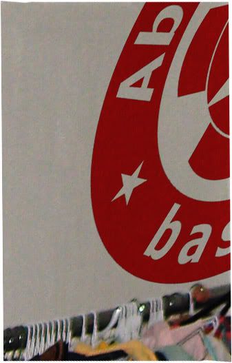
Response by poster: Vinyl Has Been Applied: Skewed view, and head-on view. All that remains is to fill in the white spaces at the seams, and then lacquer.
posted by jjjjjjjijjjjjjj at 8:47 PM on January 12, 2009 [2 favorites]
posted by jjjjjjjijjjjjjj at 8:47 PM on January 12, 2009 [2 favorites]
Best answer: WRAP-UP: Here's a link to the completed "Instructables" tutorial... and a link to the MeTa thread where I profusely thank everyone for their help. (But thanks again, anyway...)
posted by jjjjjjjijjjjjjj at 10:19 AM on January 20, 2009
posted by jjjjjjjijjjjjjj at 10:19 AM on January 20, 2009
« Older Brahmaviharas with detailed distinctions? | Why does Ubuntu/linux make it so freaking... Newer »
This thread is closed to new comments.
posted by b33j at 4:58 AM on January 9, 2009