Help me identify a piece of electronics from a pinball machine.
November 8, 2008 3:40 PM Subscribe
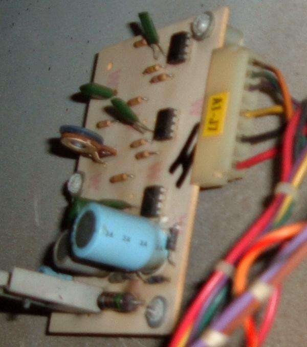
What is this device that I found inside of a Williams Grand Prix electromechanical pinball machine from approximately 1976?
Here's a photo:
http://www.skullfeed.com/thing.png
It looks like an aftermarket or enthusiast-produced part. The PCB is marked with the "nelco" brand which looks like a manufacturer of electronics supplies. None of the parts have any distinguishing marks. The 16-Pin IC on the bottom had a part number printed on top, but it has been scratched off.
I can't really tell what it's supposed to do. I'm currently repairing the machine and have not turned it on yet. Does anyone have any idea what it might be, either from a pinball machine standpoint or just in terms of general electronics?
Thanks.
Response by poster: Looks like a few go into the score relays, two lead down into the body of the cabinet and join a large cable harness. I've tried to trace the wires through the harness and they seem like they end up hooking up to a 110v fuse.
I should stress that all of this looks like it was done by someone other than an electrician.
posted by mmcg at 3:54 PM on November 8, 2008
I should stress that all of this looks like it was done by someone other than an electrician.
posted by mmcg at 3:54 PM on November 8, 2008
Uh, lower down on that page (search for 'pinball') is the mention of the pendulum tilt component.
posted by Aquaman at 4:02 PM on November 8, 2008
posted by Aquaman at 4:02 PM on November 8, 2008
It's a linear potentiometer... also known as a slide pot or slider.
Why it is there in unknown, but the normal use is for volume controls, etc.
More details if you want it, but that's exactly what it is.
posted by FauxScot at 4:03 PM on November 8, 2008
Why it is there in unknown, but the normal use is for volume controls, etc.
More details if you want it, but that's exactly what it is.
posted by FauxScot at 4:03 PM on November 8, 2008
I think that may be a very early MPU (Master Processing Unit) described at Internet Pinball Database
posted by MCTDavid at 4:15 PM on November 8, 2008
posted by MCTDavid at 4:15 PM on November 8, 2008
Any numbers/codes on the chips? What do those greenish wires coming from the bottom connect to?
At a guess, I'd say some sort of solenoid controller or voltage regulator - by the configuration the 8 pin chips look to be op amps (and the 16 pin is probably a dual op-amp package) but, without knowing device numbers or what it connects to, it's hard to say.
posted by Pinback at 4:30 PM on November 8, 2008
I concur with MCTDavid, that it may be an early MPU. FauxScot, I agree that the slider looks like a volume control, but electromechanical pins typically had chimes and dials to make sounds and count scores, so there'd be no need for a potentiometer-based volume slider... unless, as MCTDavid said, and the IPDb says is possible, is that that's an early prototype MPU.
One thing that might help: is the unit behind the backglass, or in the cabinet under the playfield?
posted by eschatfische at 4:31 PM on November 8, 2008
One thing that might help: is the unit behind the backglass, or in the cabinet under the playfield?
posted by eschatfische at 4:31 PM on November 8, 2008
Response by poster: The unit is mounted behind the backglass. One more thing: the PCB has a hand etched serial number "#00005," which may lend some weight to the MPU theory.
posted by mmcg at 4:42 PM on November 8, 2008
posted by mmcg at 4:42 PM on November 8, 2008
The other possibility -- perhaps a bit more probable than a super-rare prototype -- is that it's an add-on electronic sound card. That would explain the volume slider and the poor wiring.
My expectation of an early MPU would be that there would be many more ICs, whereas an aftermarket sound card could get by with what's there. The thing is, an aftermarket sound card would be wired to a speaker, which you didn't mention.
This may be a good thing to take to rec.games.pinball. Those people know everything.
posted by eschatfische at 4:56 PM on November 8, 2008
Rare prototype? Maybe. That looks like a hand-made circuit board - like someone made an add-on for your game to make it do something (extra) interesting. When I see a nice transformer and some hefty caps and a couple of diodes pointing in opposite directions, I see an AC->DC converter with a half-wave rectifier. Wanna give as the labels on those chips? I'm wondering if those 4 8-pin chips are 555 timers. If so, you probably do have an add on sound card.
posted by plinth at 5:54 PM on November 8, 2008
posted by plinth at 5:54 PM on November 8, 2008
Jeez... sorry, guys... (would have helped if I had read the post in its entirety.)
You can see the foil going to the chips. Could be timers (555's). Whatever it is uses two resistors in series going to a pin on the 8-pin chips, so I am betting it uses that big slider pot as a general setting for all control voltages.
Vcc would be pin 8. Ground pin 1. Threshold and discharge would be pins 6,7 connected to pin 2 (trigger) for astable operation. Plausible, except I can't see where pin 3 goes anywhere and that's the output?
( I am interpreting these chips as pointing up in the photo.) Haven't a clue on the bigger chip. Gotta be some better markings on the chips.
Bottom right... transformer for AC reduction. Two diodes for full wave rectification.
posted by FauxScot at 6:29 PM on November 8, 2008
I was a pinball tech from 1986-1991, soldering coils and stuff. From the discussion above my guess would be that this PCG controls the tilt function and the sliding control determines how sensitive the tilt function is.
posted by troy at 6:40 PM on November 8, 2008
posted by troy at 6:40 PM on November 8, 2008
plinth, FauxScot: I don't think the component config around them suits them being 555's wired as timers or oscillators (pins 6/7 have no timing capacitor connected to them, for one...). It looks more like op amps (not LM741's though) or similar wired as comparators or drivers. Odd, though, that it seems to have no inputs (or, possibly, no outputs).
posted by Pinback at 6:49 PM on November 8, 2008
posted by Pinback at 6:49 PM on November 8, 2008
Oh, and the chips appear to be pointing down in the photo (i.e. pin 1 at the bottom right). You can tell from the location of the big dimple (usually indicates the 'top' end of the chip), and if you zoom in you can sorta see the little dimple indicating pin 1.
posted by Pinback at 6:52 PM on November 8, 2008
posted by Pinback at 6:52 PM on November 8, 2008
Older, extremely basic sound cards ("tone boards") used 555s as oscillators, per plinth and FauxScot's suggestion.
Image from the Pinrepair site: those tone board cards look a lot like what you posted. Image is to a Gottlieb board, though, not an aftermarket board for a Williams, although the essentials look similar. Note the very different looking volume slider (I think) in the lower left.
posted by eschatfische at 7:44 PM on November 8, 2008
With that slider and the transformer on it, the first thing I thought of was a mod to make some or all of the lights brighter.
posted by autojack at 9:54 AM on November 9, 2008
posted by autojack at 9:54 AM on November 9, 2008
This thread is closed to new comments.
posted by contraption at 3:50 PM on November 8, 2008