How is pickup formed?
March 28, 2009 11:37 PM Subscribe
Since I fitted a new 5-way switch to Young Flabdablet's Squier Strat, it produces no signal and the output appears to be shorted to ground. To fix this, I need to understand the cables that come from the pickups.
Each pickup has a foil-shielded cable. Inside the foil are a bare wire that connects to the foil itself, and three insulated wires: a green one, a white one and a black one.
Before I messed with it, this guitar featured a horrible snarl of badly soldered connections protected at random with bits of weepy old masking tape. The black wires from all three pickups were connected together and grounded, all the bare shield wires were floating, and the green and white wires from each pickup were connected together at the selector switch.
I thought the missing shield connections were probably contributing to the thing's sensitivity to electrical noise, so I tidied up the wiring as well as replacing the selector. The black wires and shield wires are now all grounded, and the greens and whites connect together at the selector switch as before.
But now there's no output, and when I measure the resistance between a green/white pair and the black/shield pair on an unselected switch terminal, I see a short circuit.
All the pickup wiring diagrams I've found online that refer to shielded cables seem to refer to cables with four insulated conductors inside the shield. I only have three.
I can't see any manufacturer ID on the pickups themselves, which appear to be of quite shoddy construction (no metal threads for the mounting screws, magnets that fall off with evidence of past superglue repairs, threaded pole pieces pushed into unthreaded holes, and a Patent Pending sticker on one of them). The pickup bodies are a yellowish cream color.
Can anybody identify these pickups based on these wire colors, and tell me whether I've just melted all the cable insulation while soldering the shield wires, or whether there is in fact some reasonable way to design a pickup with three wires that shorts out when you connect the shield to the cold side?
How get gitter pragnet?
Here is a big list of pickup wiring diagrams, and this one is the stock wiring on a Strat. I don't know what to tell you about the three wires coming from each pickup, though: I've only ever seen two wires plus maybe a shield on all the pickups I've wired, and all the diagrams on that site show two wires as well. Then again, I've only wired basses, but the wiring should be the same.
posted by DecemberBoy at 2:05 AM on March 29, 2009
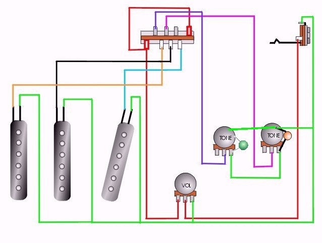
Response by poster: DecemberBoy, the wiring in this one was more like this, with the tone controls sharing a single capacitor. I'm not attempting to modify this, just to make it work with the weird shielded cables coming out of these pickups instead of the two wires per pickup arrangement. It's the likely configuration of those weird shielded cables that I'm hoping somebody can help me with, rather than what they end up being connected to.
idiopath, there are more than two wires so I guess it's pretty sure to be some kind of humbucker winding. A centre tap was my first thought as well, but it doesn't really fit with the way the thing was originally wired: black to earth (case of volume pot), green and white joined at selector switch. If A-B is first coil and B-C is second coil, then as far as I can see there are two possibilities here: either black is one of the ends (A or C), in which case connecting green and white is putting a short across the other coil; or black is the tap (B) in which case connecting green and white puts the two coils in anti-parallel. And none of this explains why my multimeter is showing me a dead short between green+white and black+shield, rather than a coil resistance, on all three pickups.
Maybe I should be looking sideways at my multimeter.
posted by flabdablet's sock puppet at 5:38 PM on March 29, 2009
Response by poster: OK, mystery solved. I fixed my crappy meter so it actually measured kilohms properly, then took apart my beautiful soldering, clipped and stripped the end of a pickup cable and measured it.
Shield - black: open
Shield - white: open
Shield - green: short
Black - white: 8K
Black - green: open
White - green: open
So they're single-coil pickups, not humbuckers; the green wire is pretty much redundant (it appears to be a pickup-end connection to the shield foil); and whoever wired this thing before me had the shield connected to the hot side.
Thanks to everybody who thought about this.
I'm off to have a bit of fun reversing the phase of the middle pickup. Let's see if we can get a bit of poor-man's humbucking action happening here.
posted by flabdablet's sock puppet at 7:38 PM on March 29, 2009
This thread is closed to new comments.
My standard protocol to fix this kind of mixup is plugging a jack into a cheap guitar pedal plugged in to a cheap solid state amp (you could blow a tube amp doing this, and putting a cheap guitar pedal before the amp means a less expensive repair/replace if you make an odd mistake) and clipping a small alligator clip to the two conductors on the jack, then disconnect all wiring in the guitar, and find the pairs of wires you want to try sending through to the amp with the alligator clips. For good measure you can test for sound before and after each solder.
posted by idiopath at 1:23 AM on March 29, 2009